=========================================================================
Reference:
- Previously Microcontroller lab 1, written by Dan Gastler (dgastler@bu.edu) and Eric Hazen (hazen@bu.edu) from BU EDF
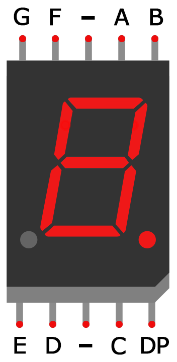
- 5161AS single 7 segment display datasheet
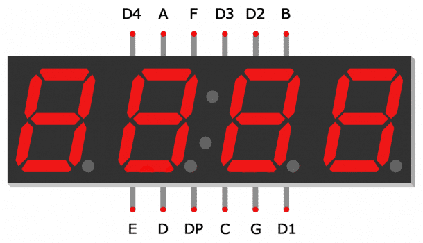
- 5641AX series Quad 7 segment display datasheet
- Arduino 7 segment display tutorial from Circuit basics
===========================================================================
Lab 2.1 Switches and LEDs
First we are going to warm up by connecting some wires (switches) and LEDs to your Arduino and programming it to emulate various types of digital logic.
- Connect the positive side (longer lead) of the 4 LEDs to different digital pins
- Connect the common side (shorter lead) of the LEDs to breadboard ground
- Connect the Arduino GND to breadboard ground
Note for switches:
- Connect another 4 wires from 4 digital pins to different switches/pushbuttons.
- You can a) manually switching the input between 0 and 5V by plugging the wire into 5V or 0V rails, or b) you can using a mechanical switch/pushbuttons (which requires careful setup)
Write a sketch which reads the “switches” and displays the value on the LEDs. Make sure you use pinMode to set the LED pins as outputs.
Use digitalRead() on each “switch” and digitalWrite() on each LED.
Note:
The input is read and set as an integer value, then it is passed into output to light up corresponding LEDs. Use the 5V from the Arduino as power supply.
Lab 2.2
Connect a push-button to a digital pin on your Arduino.
Write a sketch which counts inputs from the pushbuttons or switches in binary and displays the count on the LEDs, i.e. if you have LEDs as “1010” (off-on-off-on), it means 10 in decimal.
Lab 2.3
Modify your sketch to count seconds, and use the switch to control the starting and stopping. Display the seconds in binary on the LEDs.
Lab 2.4 7-segment display
(Specs at top of page)
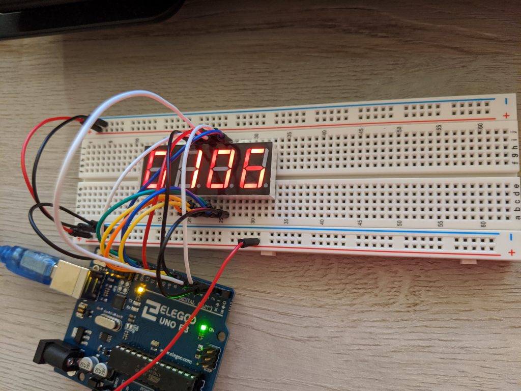
Now you are going to turn your Arduino into a digital voltmeter, which displays an unknown voltage on a 3~4-digit display. You can find the spec on top of the page.
First we need to figure out how to display information in a more convenient way than in binary on the LEDs.
Use either a single 7-segment display or with a four digit set, wire up at least one digit.
Write a sketch which outputs various values to the digital outputs.
Figure out how to display the values “0” through “9”.
Lab 2.5
Add three more digits to your display (The four digit set).
Write a sketch which displays a four-digit number. This is a bit of tricky coding — first make sure all four digit can update the same number simultaneously, then proceed to display any four-digit numbers.
Hint: Think of it as LED multiplexing
Lab 2.6
Make a simple counter which counts in 10ms increments up to 99.99 seconds (use the delay() function to delay 10ms).
Note: Do not forget the decimal point.
Lab 2.7
Create a voltage divider (or use a potentiometer) to provide an adjustable DC voltage from 0 to 5V and wire it to the A0 (analog input 0) pin of your Arduino.
Use the analogRead function to measure the voltage on the potentiometer, modify your sketch to calibrate the display so it reads in volts, i.e. from 0.000 to 5.000.


