==========================================================================
Reference:
- Previously Mircrocontroller lab 3 and lab 4, written by Dan Gastler (dgastler@bu.edu) and Eric Hazen (hazen@bu.edu) from BU EDF
===========================================================================
Reading
Pleaser read the following before class:
- Arduino Tutorial
- Accessory Kit — list of items in your kit to use today
- Introduction to Microcontrollers — Google document by E. Hazen
- (Recommended) On the Arduino Website:
After the reading, you should know how to write a sketch (program) and download it into your Arduino. You should understand the following terms:
- sketch, digital input, digital output, analog input, analog output
- variable, constant
- function, operator
- flash memory, RAM, EEPROM
Lab 1.1- Serial Communications
The USB cable from your Arduino to the computer can be used for communication of data as well as programming new sketches into your Arduino. Please read the first part of the Ladyada Tutorial (link).
Write a sketch which initializes the serial port for 9600 baud, prints a “Hello” message, and then outputs a message with a counter once per second after that. Test it using the Arduino serial monitor. The output should look something like this:
Hello World!
Seconds since start: 1
Seconds since start: 2
Seconds since start: 3
…
Lab 1.2 – Servo
A servo (such as the one in your kit) is a motor which moves over a fixed range, whose position can be set precisely based on a control signal. This servo (like most others) expects a PWM signal (we will come back in lab 3). Once it is wired up it just takes one function call to move it to a specific angle in the range 0-160 degrees
Wiring:
SERVO Black/Brown wire: GND
SERVO Red wire: +5V
SERVO White/orange wire: Arduino pin 9 (or any PWM-capable pin)
–be sure to connect Arduino GND to breadboard/external power GND
–If different wire color, check your Servo spec sheets
Programming:
#include <Servo.h>
Servo myservo; // create a servo object
// (in setup)
myservo.attach( 9, 800, 2400);
// (in loop)
myservo.write( 90); // move to position in degrees
Lab 1.3 – Light Sensor
The light sensor is a photodiode with a frequency response similar to that of your eye. They’re used in things like phones to dim the screen to match ambient light.
One annoying thing you can do is to use the light sensor to modulate a tone from a speaker. Let’s try this example from: http://arduino.cc/en/Tutorial/Tone2.
Wiring:
Light sensor LONG lead Arduino pin A0, with 12k resistor to GND
(resistor value 8k-12k is fine)
Light sensor SHORT lead +5V
Speaker lead 1 Arduino pin 9 (use built-in speaker from your breadboard or external speaker)
Speaker lead 2 GND
Programming:
void setup() { }
void loop() {
int sensorReading = analogRead(A0);
// map sensor range 10-800 to tone 120-1500Hz
int thisPitch = map(sensorReading, 10, 800, 120, 1500);
tone(9, thisPitch, 10);
delay(1); // delay in between reads for stability
}
Lab 1.4 – Force Sensing Resistor
The force-sensing resistor (user guide) is open-circuit with no force, and provides a resistance which roughly follows a power-law down to about 100 ohms.
Wiring:
Connect one terminal to GND
Connect the other to +5V through a pull-up resistor (10k is good) and also to an Arduino analog input.
Programming:
Read the analog input like in Lab 1.2. You can also connect to a speaker for audio response.
Lab 1.5 – RGB LED
An RGB LED is three LEDs (red, green, blue) in one package, so in principle any color can be produced by mixing. It is the big fat LED with four leads (a few kits don’t have them). The long lead is the common cathode (GND) connection.
Orient the LED so that the leads point down and the long lead is 2nd from the left.
Then the pins are (R, GND, G, B) from left to right.
Wiring:
Long lead GND
Leads 1, 3, 4 Arduino PWM-capable pins (i.e. 3, 5, 6)
Through 100 ohm resistors
Programming:
Use analogWrite() to set the relative intensities of R/G/B.
The “RGB” color space is not intuitive for picking specific colors, so often an alternative such as “HSV” (Hue, Saturation, Value) is used. The algorithm for converting is well-documented here:
http://en.wikipedia.org/wiki/HSL_and_HSV#From_HSV
Lab 1.6 – Accelerometer
For this lab, we are using a newer model of the accelerometer — MMA8452, different from the old kit (the old version is obsolete now).
Use the “Example Hookup” in https://learn.sparkfun.com/tutorials/mma8452q-accelerometer-breakout-hookup-guide
as well as the “Example Code” to perform acceleration measurement.
Above website in pdf form
Backup: Download library file
================================
Lab 1.7 Stepping motor
CAUTION! The resistors get hot enough to burn you when the motor has run for a while.
This is ok… that’s why we use 10W resistors.
There are several types of motors commonly used in robotics and other applications where precise control is needed. One of the most common is the stepping motor, which can provide exact, repeatable positioning. Today you are going to build an interface circuit to drive a stepping motor from your Arduino. You need the following parts, which should be available in the lab:
- (1) Eastern Air Devices stepping motor
- (4) IRF520 N-Channel power MOSFET transistors
- (4) 1N4001 diodes
- (2) 20 ohm 10W power resistors
- (1) power supply capable of delivering 12V at ~ 1A
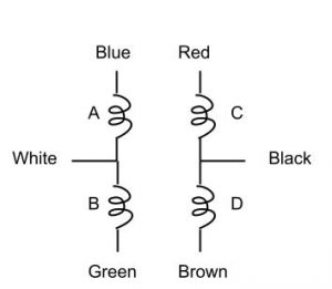
Eastern Air Devices motor windings diagrammed below. Possibly yours will have different colors. Each winding should be about 6 ohms; verify the wiring with your ohm-meter.
The basic challenge in driving a stepping motor is to energize the motor windings in the correct sequence, which causes the motor to rotate in discrete steps. The motor we are using is a precision one, with 1.8 degree full steps and 0.9 degree half steps. From Jones we read that you energize the windings in the following typical sequence for full-step operation:
| ABCD |
| 1010 |
| 1001 |
| 0101 |
| 0110 |
A ‘1’ represents an energized winding, with the bit positions representing the four windings A, B, C, D as shown in the diagram above. For “full step” operation with two windings energized at a time, the motor rotates 1.8 degrees per step. The following trajectory will half-step the motor, resulting in 0.9 degrees per step but slightly reduced torque:
| 1010 |
| 1000 |
| 1001 |
| 0001 |
| 0101 |
| 0100 |
| 0110 |
| 0010 |
The motor windings require much more current (about 1 Amp) than the Arduino can provide directly from it’s digital outputs, so we use a power MOSFET as a switch. The principle is the same as for the small MOSFETs you used to make logic gates in an earlier lab. We are using an N-Channel enhancement mode MOSFET, which behaves like an NPN bipolar transistor, with the source connected like the emitter, and the gate connected like the base. An enhancement mode MOSFET is “normally off” and requires a positive VGS (gate-source voltage) to turn it on. For the IRF520 MOSFET, a VGS of at least 5V is required for turn on. This voltage can be provided directly by the Arduino digital outputs.
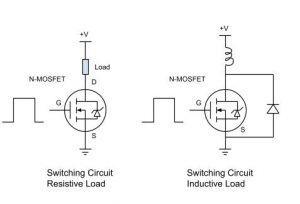
Typical MOSFET power switching circuits are shown in the figure below. For a resistive load (i.e. a high current lamp) the circuit is very simple; just connect the load between the drain terminal and an appropriate positive supply. For an inductive load such as a motor winding, a diode is required to dissipate the energy stored in the inductor, which would otherwise cause a potentially large voltage spike when the switch is opened which could damage the MOSFET. The IRF520 has a hefty diode built-in so we don’t need a diode there.
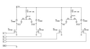
Below is the full schematic for the drive circuit for the stepping motor. The boxes with color names represent the connections to the motor, while the flags with signal names A/B/C/D represent connections to Arduino digital outputs.
(Click to enlarge the circuit)
Notice that there are now diodes in a new position in the circuit. The reason for this is slightly subtle. Each pair of windings acts like an auto-transformer. Briefly, this means that the magnetic field produced when one half of the double winding is energized produces a potential in the other half which could exceed the voltage rating on the MOSFET. The diode prevents the other end of the winding from going above the 12V supply.
Construct the circuit shown above on your breadboard. Since relatively large currents and voltages are involved which could damage the Arduino, be extra careful to wire everything correctly. Check the pinout of the MOSFET carefully with the datasheet. Wire the signals A/B/C/D to digital outputs on your Arduino.
Write a sketch which will turn the A/B/C/D outputs on in sequence as shown in the either full-step or half-step table above. Add a delay of 10 ms after you update all four outputs.
Lab 1.8
Write a function in your sketch with the prototype:
void run( int steps, int speed)
where steps is the number of steps to turn (negative numbers for reverse direction) and speed is the variable to control the rotation speed. What is the fastest speed the motor will run at reliably?
Lab 1.9
Modify the sketch to accelerate the motor gradually instead of starting at full speed. Can you run reliably at higher speed now?


