7-26-00
Sections 23.9 - 23.10
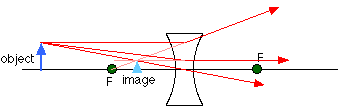
Consider now the ray diagram for a diverging lens. Diverging lenses come in a few different shapes, but all diverging lens are fatter on the edge than they are in the center. A good example of a diverging lens is a bi-concave lens, as shown in the diagram. The object in this case is beyond the focal point, and, as usual, the place where the refracted rays appear to diverge from is the location of the image. A diverging lens always gives a virtual image, because the refracted rays have to be extended back to meet.
Note that a diverging lens will refract parallel rays so that they diverge from each other, while a converging lens refracts parallel rays toward each other.
We can use the ray diagram above to do an example. If the focal length of the diverging lens is -12.0 cm (f is always negative for a diverging lens), and the object is 22.0 cm from the lens and 5.0 cm tall, where is the image and how tall is it?
Working out the image distance using the lens equation gives:

This can be rearranged to:

The negative sign signifies that the image is virtual, and on the same side of the lens as the object. This is consistent with the ray diagram.
The magnification of the lens for this object distance is:

So the image has a height of 5 x 0.35 = 1.75 cm.
Many useful devices, such as microscopes and telescopes, use more than one lens to form images. To analyze any system with more than one lens, work in steps. Each lens takes an object and creates an image. The original object is the object for the first lens, and that creates an image. That image is the object for the second lens, and so on. We won't use more than two lenses, and we can do a couple of examples to see how you analyze problems like this.
A basic microscope is made up of two converging lenses. One reason for using two lenses rather than just one is that it's easier to get higher magnification. If you want an overall magnification of 35, for instance, you can use one lens to magnify by a factor of 5, and the second by a factor of 7. This is generally easier to do than to get magnification by a factor of 35 out of a single lens.
A microscope arrangement is shown below, along with the ray diagram showing how the first lens creates a real image. This image is the object for the second lens, and the image created by the second lens is the one you'd see when you looked through the microscope.
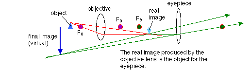
Note that the final image is virtual, and is inverted compared to the original object. This is true for many types of microscopes and telescopes, that the image produced is inverted compared to the object.
The sign convention for lenses is similar to that for mirrors. Again, take the side of the lens where the object is to be the positive side. Because a lens transmits light rather than reflecting it like a mirror does, the other side of the lens is the positive side for images. In other words, if the image is on the far side of the lens as the object, the image distance is positive and the image is real. If the image and object are on the same side of the lens, the image distance is negative and the image is virtual.
For converging mirrors, the focal length is positive. Similarly, a converging lens always has a positive f, and a diverging lens has a negative f.
The signs associated with magnification also work the same way for lenses and mirrors. A positive magnification corresponds to an upright image, while a negative magnification corresponds to an inverted image. As usual, upright and inverted are taken relative to the orientation of the object.
Note that in certain cases involving more than one lens the object distance can be negative. This occurs when the image from the first lens lies on the far side of the second lens; that image is the object for the second lens, and is called a virtual object.
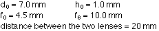
Let's use the ray diagram for the microscope and work out a numerical example. The parameters we need to specify are:
To work out the image distance for the image formed by the objective lens, use the lens equation, rearranged to:

The magnification of the image in the objective lens is:

So the height of the image is -1.8 x 1.0 = -1.8 mm.
This image is the object for the second lens, and the object distance has to be calculated:

The image, virtual in this case, is located at a distance of:

The magnification for the eyepiece is:

So the height of the final image is -1.8 mm x 3.85 = -6.9 mm.
The overall magnification of the two lens system is:

This is equal to the final height divided by the height of the object, as it should be. Note that, applying the sign conventions, the final image is virtual, and inverted compared to the object. This is consistent with the ray diagram.