INTRODUCTION
Many of you have seen the Thevenin equivalent circuit — how to transform a complicate circuit into a simple one. Even a simple op amp is consisted of many components:
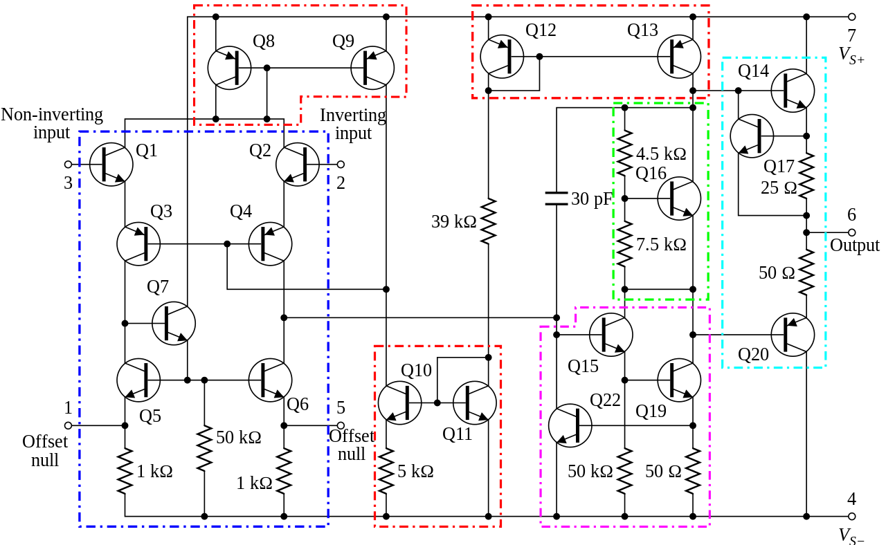
Image source: Texas Instruments.
Due to its complexity, a more common approach is to view it as a black box with input/output:
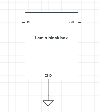
However, the black box itself must has some resistance/impedance, and this affect how we integrate this box in practical use — will this box drain too much current since it has very low resistance, or will this box taking most of the voltage drop since it has a high resistance?
==================================
INPUT IMPEDANCE
The definition of the input impedance: “How much impedance(resistance) from the point of view of the INPUT”
— It determine how much current you need to draw from the input (simply Ohm’s Law)
— It determine how much voltage will be shared by the black box (remember the input also has internal resistance)
— Has NOTHING to do with the output. (Don’t attempt to look at the output to determine the input impedance)
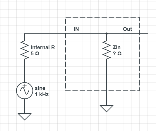
Let’s put a function generator on the black box input:
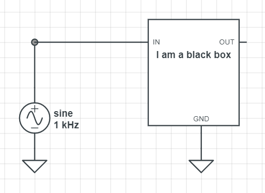
But nothing is perfect, all input device has some amount of internal resistance, so:
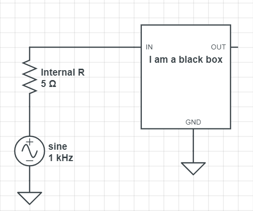
To simplify, we will treat the black box as one big resistor, with its resistance being the input impedance (Zin):
Let us think for a moment:
- If the Zin is small:
- The function generator will draws lots of current due to low resistance, may even damage the device
- Lots of voltage will goes to the internal resistance, waste lots of power, and very few signal actually reach the black box.
- Has to increase input voltage to compensate the loss — not economic.
- If the Zin is large:
- By Ohm’s law, large resistance implies low current.
- Most of the voltage will go into the black box, since internal resistance is small and won’t take much of voltage drop.
- Don’t need to worry about electric bill
So… how to we determine the input impedance then? Since the circuit now is nothing but resistors in series, we can add a test resistor on the input:

Compared to the 20k test resistor, the 5 ohm internal R is almost nothing — we can safely assume that the test resistor and Zin will take most of the voltage drops.
So it kind of looks like this now:
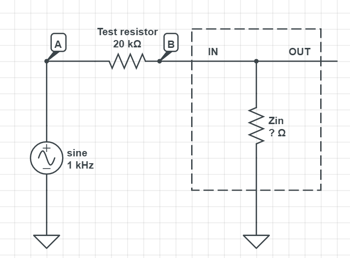
This is nothing but two resistors in series — a simple voltage divider.
To calculate Zin, you can:
- Measure the voltage amplitude on point A and B, and use the ratio to calculate Zin, or:
- Put a different test resistor, until the voltage amplitude at B is HALF of the voltage at A — implies the new test resistor value is the SAME as the Zin
Congratulation, you just measure the input impedance!
*A good circuit should have high input impedance.
*Some special device are sensitive to the input frequency (like capacitors). If unsure, change the input frequency and measure the input impedance again.
==========================================================================
OUTPUT IMPEDANCE
The definition of the output impedance is ” “How much impedance(resistance) from the point of view of the OUTPUT”
— It determine how much voltage will be shared between the black box and the output load
— The input amplitude DOESN’T MATTER. (Don’t attempt to look at the input to determine the output impedance, since your black box may transform your input signal anyway)
Let’s put a function generator on the black box input (we still need send in some signal, otherwise we won’t see anything):
Since we are looking the black box from the point of view of output, the input signal may have been transformed by the black box and have a different wave form, so we can turn it into a Thevenin equivalent circuit:
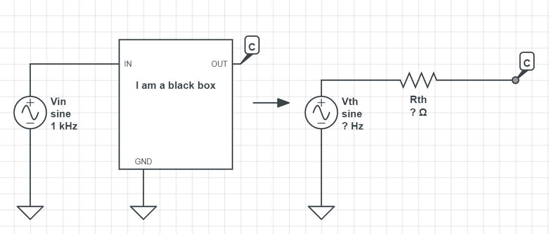
And Rth will be the output impedance. We can also call it Zout.
Let us think for a moment:
- If the Zout is small:
- With small resistance, Zout won’t have too much voltage drop, so most of the signal from Vth can pass into the next stage.
- If the Zin is large:
- Unfortunately, lots of voltage from Vth will be applied on Zout, and only a portion of the Vth can pass into the next stage.
Now, in order to calculate Rth, we need to know the voltage of Vth — you can simply measure it with a scope at point C. Since an ideal scope has ~infinite resistance (or ~10 megaohm in reality), so most Vth can be loaded on the scope.
We now can add a load resistor to the circuit:
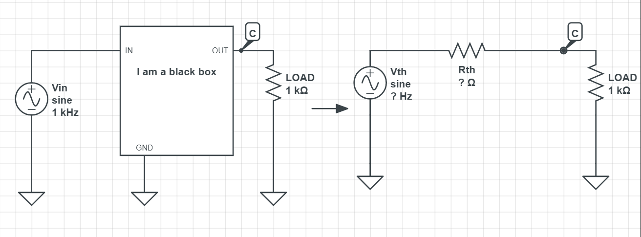
With the load resistor added, measure the voltage amplitude at point C and you should see a smaller amplitude than the Vth. By now we know the amplitude of Vth (the total voltage), the amplitude of voltage on the load resistor, and the resistance of the load, it should not be tough to calculate the value of Zout.
Similar to the input impedance, you can vary the load resistance until the value you measure on point C is HALF of Vth, which implies this chosen load resistance is the SAME as Rth (or Zout).
Congratulation, you just measure the output impedance!
*A good circuit should have low output impedance.