Below is the eLab scope & DVM tutorial procedure, make sure you watch the tutorial video for both DVM and oscilloscope before performing any physical operation.
If you encounter any questions along the way, don’t hesitate to contact the instructors to assist you.
Part 1: Understanding DVM (Digital Volt Meter) & DC
- An Arduino board has built-in 5V and 3.3V DC power supply. Can you use your DVM to check these two voltages?
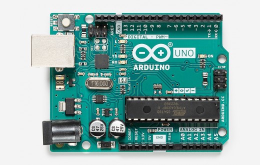
You can see the 5V and 3.3 V label at the bottom pins. Source: Arduino store
- Once you can verify your Arduino DC power supply is functioning, make yourself a voltage divider: with two 10k ohm resistor in series, and use the DVM to check if you can obtain ~2.5V and ~1.65V from one of the resistors.
Part 2: Understanding oscilloscope
You will learn how to use the oscilloscope. By default, the channel 1 probe is connected to the calibration wave. You can:
- Try out different buttons/knots to see what it does. For example, horizontal/vertical scale, displacement, trigger, etc.
- After experimenting different settings, can you go back and show the original pictures?
- Learn how to “compensate” your scope.
Part 3: Detect real signal
Remember during the first week, you download the PWM code for the Arduino for lighting up 5 different LEDs? Now, you can use the scope to see what kind of signals that give the LED different intensities:
- Starting by connecting the channel 1 to one of the Arduino output pin that previous connected to those LEDs (pin 3, 5, 6, 9, & 10). What do you see on the scope? Try to “trigger” it to show a stabilized image.
- Use two cables with grabbers, one for channel 1 and another for channel 2, and have them connected to different output pins. Manipulate the scope to position the channel 1 signal on the top half of the screen and the channel 2 signal on the bottom half of the screen, and adjust the time scale to display at at least two periods of the detected signal. What differences can you see between these two channels? Try different pins.
- How do you determine the amplitude, frequency, and pulse width of each signal?
You are almost done! Inform any instructors to review your result and check out.