In this exercise you will test & run the example programs provided by the Arduino software, as well as to build your first LED digital circuit for this class.
Step 1: Download your Arduino
- Go to https://www.arduino.cc/en/main/software and download the Arduino software based on your operating system.
- Install the Arduino software
Step 2: Connect your Arduino board to laptop
- Connect your Arduino and laptop with the provided USB cable
- Open the software, make sure that under “Tools -> Board:” your Arduino board type (UNO if your bought the kit) is shown
- Make sure that under “Tools -> Port” It shows the correct COM port for your Arduino USB port (It may also auto-detect the port on your system already)
Step 3: Try the Blink tutorial
- Select “File -> Examples -> 01.Basics -> Blink” to open the Blink program
- Press the “upload” button…
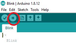
- … to upload the program and wait for it to finish. You should see the LED on the Arduino board starts blinking!
- By default, the blink happens every other second. To change the frequency, you can change the value inside delay(1000), upload the code again to see the result.
Step 4: Try the Fade tutorial
Now you are going to build the simplest circuit for the Fade tutorial. Find the following components from your Arduino kit: breadboard, LED (Any color), wire:
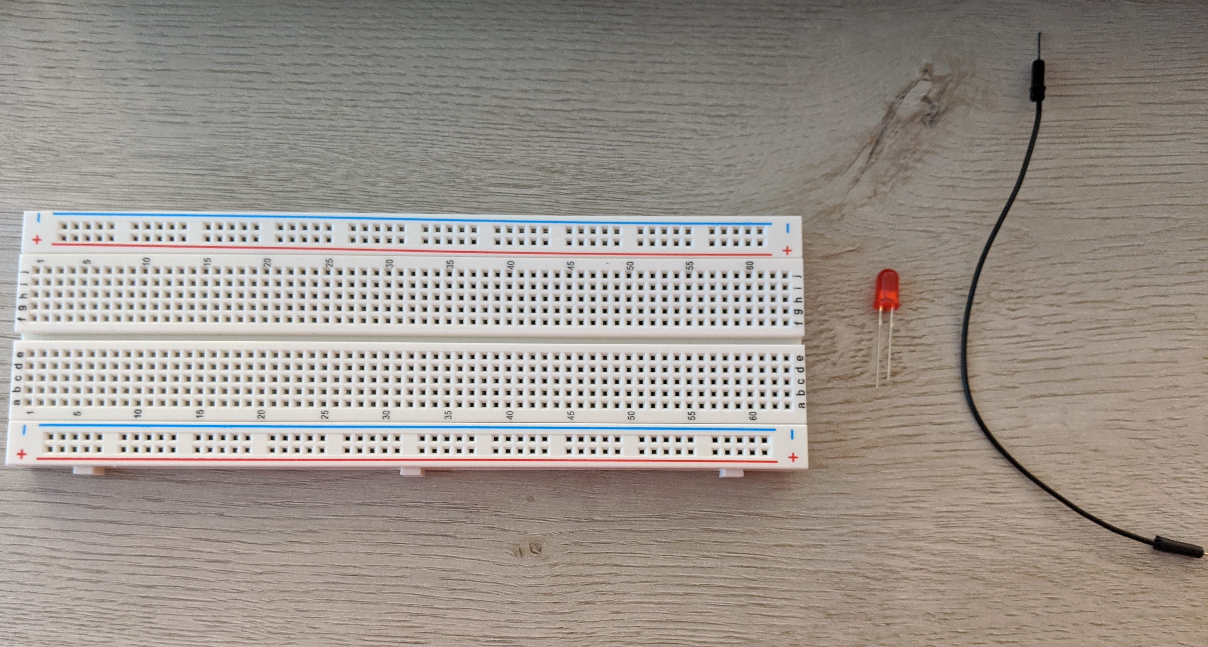
Notice that the LED has two lead: The longer lead is positive (+) and the shorter lead is negative (-), indicate the direction of current flow, from (+) to (-).
Now connect the components:
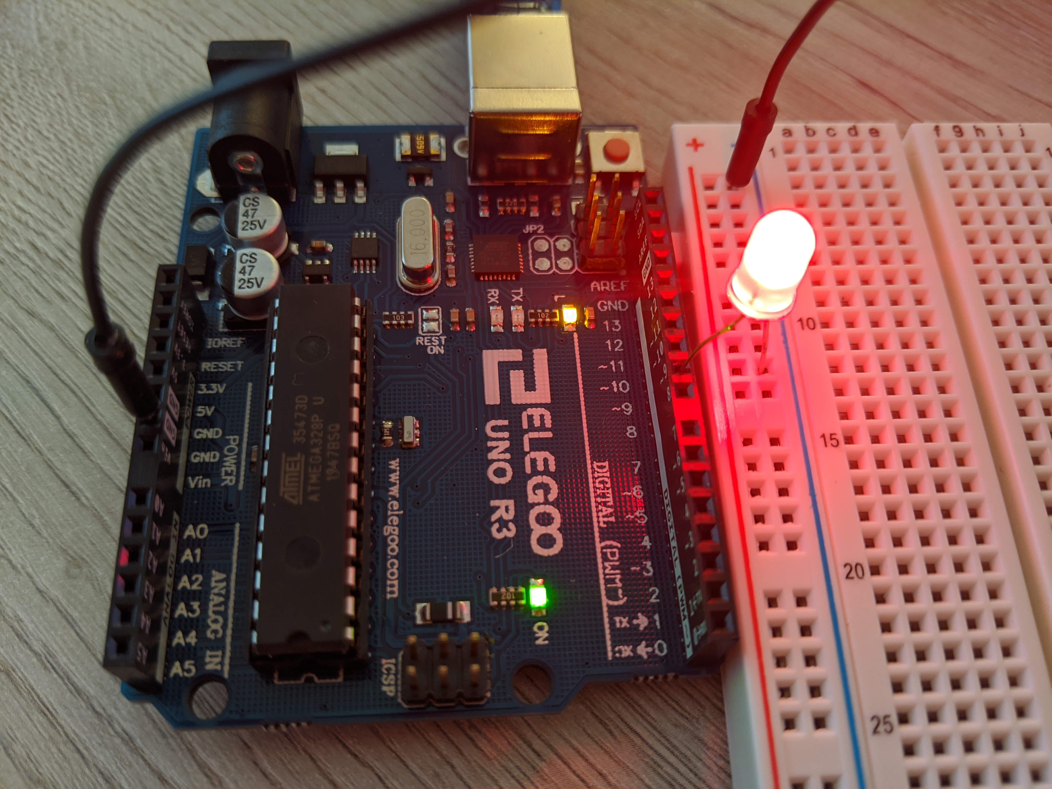
- Put one end of the wire to the GND pin (there are several on the board) and another end to the vertical blue (-) rail on breadboard.
- Put the positive end of the LED to digital pin 9 (label ~9) on the Arduino board. Put the negative end of the LED to the vertical blue (-) rail on breadboard.
- When finished, select the Fade code from “File -> Examples -> 01.Basics ->Fade” and upload the program. You should see the result similar to the above photo, with the LED intensity varying.
Step 5: Try the PWM (Pulse-Width-Modulation)
- First download the customized code here: Link
- You will need four more LEDs in addition to the one you have above. Choose any color you want.
- The black wire will remain in its previous connection
- All of these five LEDs will have their negative end connected to the LED to the vertical blue (-) rail on breadboard, and their positive end will be connected to different pins: 3, 5, 6, 9, 10. See the picture below:
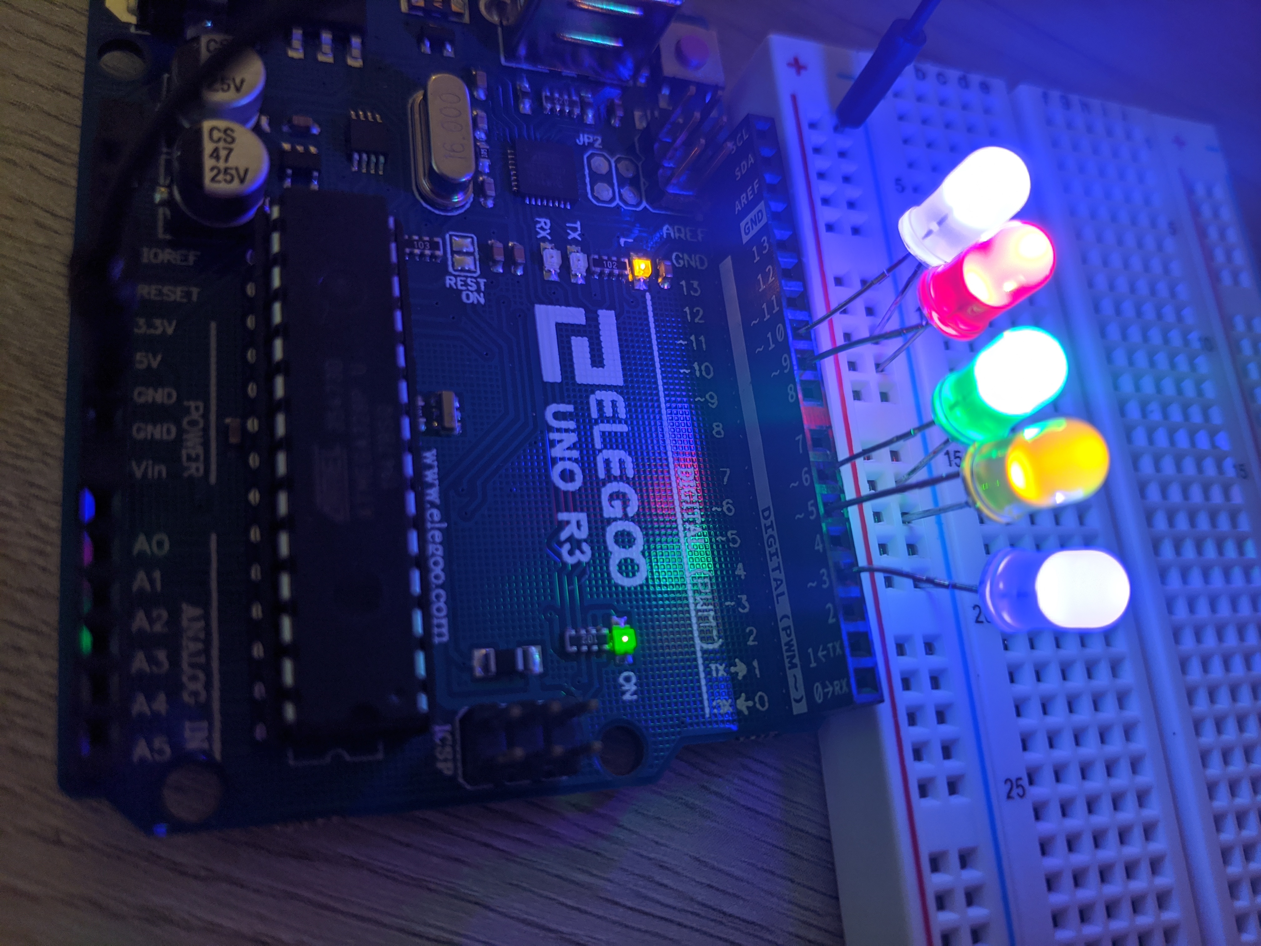
- Upload the program to see its result. The higher the pin number, the higher intensity you will have on the LEDs.
You now finish the Arduino practice!