=========================================================================
Reference:
- Previously Microcontroller lab 5, written by Dan Gastler (dgastler@bu.edu) and Eric Hazen (hazen@bu.edu) from BU EDF
- “Using ADS1115 Module with Arduino” by CyberBlogSpot.
==========================================================================
Lab 4.1 – Oscilloscope v1
Connect a function generator to the A0 pin on your Arduino through a small resistor (1k or so). Ground the Arduino to the generator or breadboard.
Write a sketch which reads the A0 pin using analogRead() and prints the output to the serial port in loop().
Set the function generator to generate a square wave of about 10Hz swinging between about 1V and 2V. What do you see in the serial monitor?
(Hint: unplug the USB cable to get the output to stop so you can look at it).
- Look at the waveform on the oscilloscope and sketch it
- Cut/paste the list of numbers from the serial monitor into a spreadsheet or other plotting program and make a plot. Compare it with the oscilloscope picture.
They should look quite similar.
Congratulations! You have made a digital oscilloscope. It’s not very easy to use, though.
There are two glaring problems with your first oscilloscope. It sends data continuously rather than in convenient pieces, and the sampling rate is determined by how fast the data can be sent to the computer.
▢ Estimate the sampling rate. The “baud rate” is 9600, which is the number of bits per second sent. Each byte takes 8 bits (plus a start and stop bit) so the rate of sending bytes (characters) is about 1/10 of the baud rate.
Lab 4.2- Oscilloscope v2
Now we’re going to make a new version which addresses the problems above.
Write a new sketch which does the following:
- waits for a character to be received from the computer
- sends 100 samples, collected at 1 sample per 1ms (use delay()).
NOTE: you must collect the samples in an array in one loop, then send them to the computer in a separate loop.
A couple of tips. To wait for one character from the computer, use this code:
while( Serial.read() == -1) { }
Serial.read() returns -1 if there is no character to read. The loop body is empty because there isn’t anything to do while we’re waiting.
Test it. Set the signal generator to 100Hz. You should see about 10 cycles in the waveform. It won’t be exact because delay() is not a very accurate way of controlling the sample rate.
Lab 4.3 – Oscilloscope v3
Now we’re going to make the sample rate more precise, and adjustable.
Modify your sketch to use the TimerOne library as you did before (look back at the notes if you need to). The sample rate will be the parameter to Timer.Initialize() in uS. Note that the ADC is fairly slow, so values below about 100uS will begin to give poor results.
Set two constants at the top of the code:
const unsigned int sample_interval_us = 100;
const unsigned int record_length = 100;
Your sketch should use these to set the sampling interval and number of points.
It should also trigger only when it receives a character from the computer.
You will need to figure out a way to make the timer interrupt capture the specified number of samples in response to a trigger and then stop. The best way to do this is to declare a variable to count the number of samples recorded, and an array to store the samples in, like this:
int waveform[record_length];
volatile int num_samples;
(“Volatile” is a modifier required for all variables shared between interrupt routines and the main program).
Then the timer interrupt looks something like this:
void timer_func() {
if( num_samples < record_length)
waveform[num_samples++] = analogRead( A0);
}
The main loop would wait for a character, and then set num_samples = 0 to start data recording. Sampling is done when (num_samples == record_length).
Test it at various sampling rates and various frequencies of the signal generator.
Lab 4.4 – Improved ADC capability with ADS1115 16 bit ADC
Since the Arduino come with a 10 bit resolution on the ADC, your measurement is limited by its ~5mV resolution. Here we are going to use a 16 bit external ADC to improve our capability to have a ~80uV resolution.
First, connect the ADS1115 to the Arduino as below:
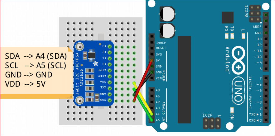
Choose a potentiometer, with the center pin wired to A0 on the ADS1115 module, and connect to other two pins to 5V and ground (give you a voltage swing between 0 to 5V).
Install the new library ADS1x15, by Rob Tillaart, (you can also download it here) then use the example code ADS_read provided by the library
Open the serial monitor and you should see a similar output:
Analog0: 26239 4.91996
Analog1: 5961 1.11772
Analog2: 5884 1.10328
Analog3: 5911 1.10835
With the first column being the raw ADC readout and the second column displays the converted voltage value.